
How Does a 3D Crane System Work?
Understand the Complete Workflow of a Modern 3D Crane System
A 3D Crane System combines positioning technology, intelligent sensors, and digital construction models to guide crane operators during lifting operations. This guide explains the complete working process from project setup to precise load placement.
Introduction
Modern construction projects require heavy materials to be placed with a high level of accuracy. Steel beams, bridge segments, precast concrete panels, wind turbine components, and industrial equipment often need to be installed within a few millimetres of their design position.
Traditional lifting methods rely heavily on the operator’s experience and hand signals from workers on the ground. A 3D Crane System improves this process by providing real-time positioning, live measurements, and digital guidance directly inside the crane cab.
The system continuously calculates the position of the crane, boom, hook, and load, allowing operators to work more accurately, safely, and efficiently.
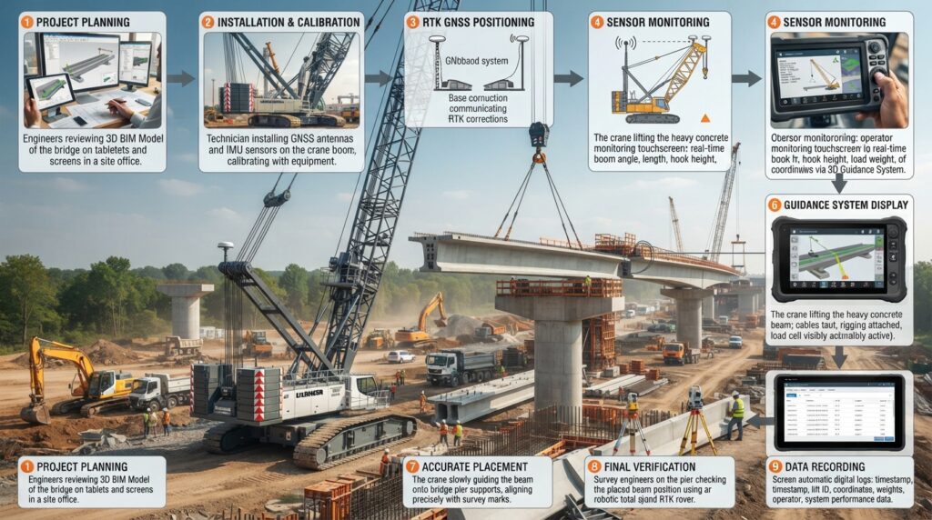
Step 1 – Project Planning
Before lifting begins, engineers prepare the lifting plan.
The project drawings or 3D design model are loaded into the crane’s machine control software. Engineers define lifting locations, installation points, lifting heights, and safe working areas.
This digital model becomes the reference for the entire lifting operation.
Step 2 – Install and Calibrate the System
The crane is equipped with various sensors and positioning devices.
Before work starts, technicians calibrate all equipment to ensure accurate measurements.
Typical components include:
- GNSS Receivers
- IMU Sensors
- Boom Angle Sensors
- Boom Length Sensors
- Hydraulic Pressure Sensors
- Load Moment Indicator (LMI)
- Hook Position Sensors
- Onboard Computer
- Touchscreen Display
After calibration, the system checks communication between all sensors.
Step 3 – Determine the Crane Position
The GNSS receiver continuously calculates the exact location of the crane.
If higher accuracy is required, the crane may receive corrections from an RTK GNSS base station or network.
For indoor projects or locations where satellite signals are blocked, a robotic total station or local positioning system may be used instead.
Step 4 – Monitor the Boom and Hook
As the operator moves the boom, the sensors continuously measure:
- Boom Length
- Boom Angle
- Boom Rotation
- Hook Height
- Hook Position
- Machine Tilt
The onboard computer combines this information to calculate the exact position of the suspended load in three-dimensional space.
Step 5 – Lift the Load
The operator carefully lifts the material while monitoring the display inside the cab.
The system shows:
- Live Load Position
- Target Location
- Boom Reach
- Hook Height
- Safe Working Radius
- Load Weight
- Ground Elevation
- Clearance from Nearby Structures
This information allows the operator to move the load smoothly and accurately.
Step 6 – Follow the Digital Design
The touchscreen displays the digital construction model together with the real-time position of the crane.
Instead of relying only on visual judgement, the operator follows the digital guidance displayed on the screen.
The system continuously compares the current load position with the planned installation point.
Step 7 – Place the Load Accurately
When the load reaches the target location, the system helps the operator make small adjustments.
The operator slowly lowers the material until it reaches the exact design position.
This process greatly reduces installation errors and minimizes the need for repositioning.
Step 8 – Verify the Installation
After placement, survey engineers verify the final position using survey equipment.
Common verification methods include:
- RTK GNSS Survey
- Robotic Total Station
- Laser Scanner
- Digital Level
- BIM Verification
If necessary, small corrections can be made immediately.
Step 9 – Record the Operation
Many modern crane systems automatically record important project information.
Typical recorded data includes:
- Lift Time
- Load Weight
- Boom Position
- Hook Position
- Lift Height
- Operator Information
- Machine Status
- Working Hours
These records help with quality control, maintenance planning, and project documentation.
Safety Features of a 3D Crane System
Modern crane guidance systems include several built-in safety functions.
These include overload warnings, working radius monitoring, boom angle limits, anti-collision systems, wind speed monitoring, outrigger stability checks, and emergency alarms.
These features help reduce accidents and improve overall job site safety.
Best Practices
Always inspect the crane before beginning work.
Calibrate the sensors regularly.
Use the latest project design files.
Maintain communication between the crane operator, signal person, and survey team.
Do not exceed the crane’s rated lifting capacity.
Monitor weather conditions, especially wind speed, before lifting heavy loads.
Follow the manufacturer’s operating procedures and maintenance schedule.
Conclusion
A 3D Crane System combines advanced positioning technology, intelligent sensors, and digital construction models to make lifting operations safer and more accurate. By providing real-time guidance and continuous monitoring, the system helps operators place heavy loads with confidence while reducing errors, improving productivity, and supporting successful project completion.